

Kurbelwelle
Die Kurbelwelle ist ein zentrales Bauteil eines jeden Motors. Sowohl bei Kraftmaschinen wie Dampfmaschinen, Verbrennungsmotoren, Stirlingmotoren und Flammenfressern als auch bei Arbeitsmaschinen wie Kompressoren und Speisewasserpumpen. Zu der Aufgaben der Kurbelwelle gehört die Umwandlung der Pleuelstangenkraft in eine Drehkraft, um so ein Drehmoment zu erzeugen. Zudem gibt die Kurbelwelle den größten Teil des Drehmoments, über das Schwungrad, an der Verbraucher weiter. Des weiteren treibt sie, bei vielen Kraftmaschinen mit einem kleinen Teil des Drehmoments, die Ventilsteuerung oder eine Ölpumpe und eventuell den Zündverteiler, einem Excenter , die Motorkühlung oder einem Generator an.
Die Kurbelwelle ist durch die Pleuelstange mit dem Kolben verbunden. Auf der Kurbelwelle ist auch das Schwungrad befestigt und eine Riehmenscheibe oder Kupplung zur Kraftabnahme.
Die Form der Kurbelwelle wird durch die Art das Motors, die Zylinderanzahl, die Anzahl der Kurbelwellenlager, der Größe des Hubes und der Anordnung der Zylinder bestimmt. Kurbelwellen werden vom Modellbau bis hin zu riesigen Motoren in der ganzen Welt verbaut und hergestellt.
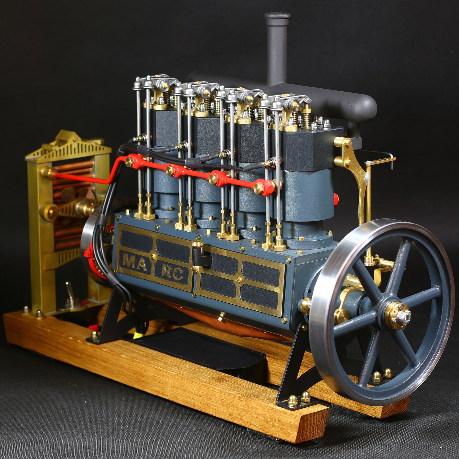
The 4-cylinder in-line engine "Marc" is based on a historical model. The model was a four-cylinder in-line engine that was manufactured by the American company Holt at the beginning of the 20th century. This engine was mainly used in bulldozers and tracked tractors. This engine was available in 2, 4 and 6 cylinder versions. In 1925, the Holt company became the Caterpillar company, which still exists today. The engine does not consist of a cast engine block, as was usual later, but still has individual cylinders. This design is visually very appealing and makes it possible to offer the engine as a material kit. Speed control via centrifugal governor Carburetor with adjustable throttle valve Cooling circuit with cooling water pump Cooler with fan With the 4-cylinder in-line engine "Marc" material kit, you can build a fully functional combustion engine yourself. The material kit contains all the necessary parts including the ignition. The engine has a functioning speed control using a centrifugal governor. A cooling water pump pumps water through a radiator, where the cooling water is cooled down by the fan and then flows back into the cylinder jacket. The engine is equipped with glow plugs. The glow plugs come with four Batteries operated. All components for producing the ignition are included (batteries are not included).Dimensions of the model combustion engine 'Marc': Height with wooden base: 310mm Length: 450mm Width: 180mm Piston diameter: 23mm Flywheel D.: 1x140mm 1x80mm Speed speed: 200-1000 rpm Weight: 9.1kg The engine stands on two oak runners. The engine block is screwed together from milled parts. The base plate for the cylinders is made of steel, the bearing blocks that hold the crankshaft are made of aluminum. This unit is then provided with finished lasered and folded sheets. The cylinder sleeves are made of brass, the inside diameter no longer needs to be machined. The cylinder head and cylinder are included as material sections and must be machined on the lathe. The remaining components are mainly made of brass. The crankshaft is made from individual segments. No milling machine is required to produce the crankshaft either. It can be built entirely on the lathe. Further information can be found in our build report for the four-cylinder engine. The two flywheels are available in the quality we know. Both flywheels are made of cast steel. The speed of this model is controlled via the carburettor. You can regulate the amount of air supplied. The carburettor is connected to a centrifugal governor via a linkage. This means you can set the engine to a desired speed, which is then maintained under load using the centrifugal governor. Here you will find an extensive construction report of the four-cylinder internal combustion engine Marc< /a> with lots of pictures and additional texts. Here you will find extensive assembly instructions for the combustion engine On the page you can see how you have to put all the manufactured parts together. Here you will find extensive instructions for the Commissioning and operation of the four-cylinder engine Marc All materials required to build the internal combustion engine "Marc" screws, nuts, springs and ignition parts are included in the kit. All milled parts are prepared so that they only need to be deburred and possibly drilled. To build the vertical stationary motor, a lathe, a drill and a gas burner for soft soldering are required. The following hand tools are also required (tap M2, M3, M4, M5, 6x0.75, M8x0.75, M10x1 die M2, M3, M5, M6x0.75, M8x0.75, M10x1 reamer 4H7 6H7, 8H7, 10H7) Files and a drill set are necessary. All you need to wire the ignition is a pair of side cutters, wire strippers and a soldering iron. If you would like to find out in advance what steps you will take to make this internal combustion enginehave to be carried out, take a look at the construction report of the 4 cylinder combustion engine "Marc" material kit in our Bengs model building magazine. On this page you can see the illustrated report on how the stationary motor material set is processed.The scope of delivery includes: finished CNC milled milled parts Raw material for the turned parts Rough casting part for the flywheels 2 runners made of oak wood All required screws, nuts, gears and seals Drawings of the internal combustion engine "Marc" (36 sheets) and construction instructions (8 sheets) Glow plugs, cables, cable clamps, battery compartment for the ignition Laser parts for stands and fairings
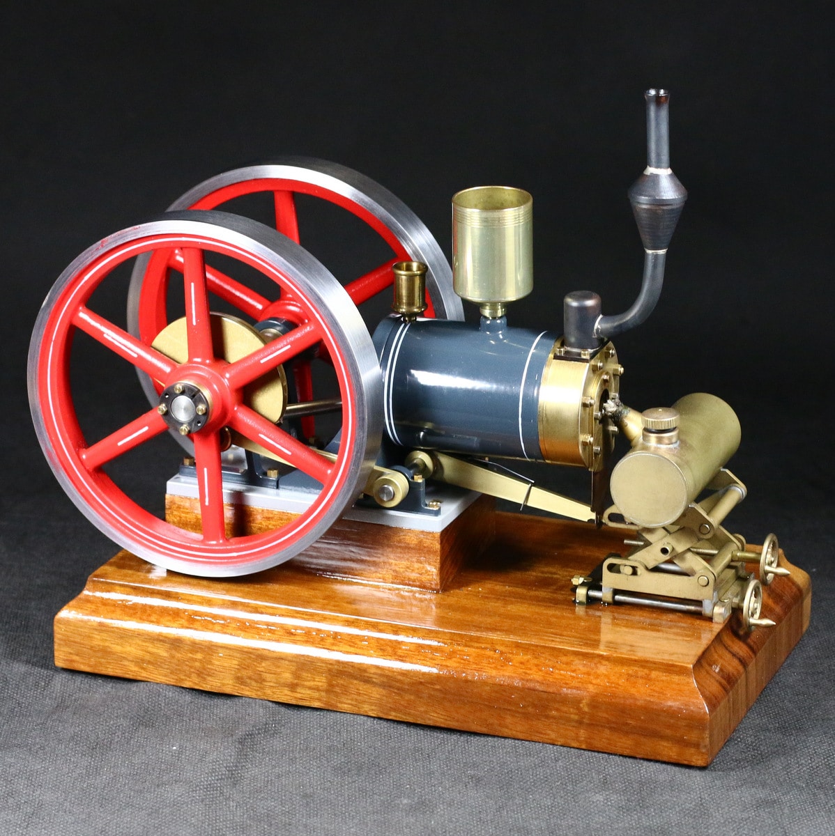
The vacuum motor or flame licker 'The large Nick' mainly consists of brass. It possesses water-cooling with an evaporator container. The flywheels are made of cast iron. The large Nick is mounted onto a Jatoba wood plate. The crankshaft and the slide shaft have ball bearings. It runs at approx. 200-300 rpm. The burner is adjustable in height, so that the speed can be regulated over the handhweel. In addition, the distance from the flame to the cylinder head can be adjusted over a handwheel. All milled parts have already been processed and must be partially drilled yet. All rotating parts are yet to be filmed in its raw state and need. The construction of the fire-eater and the burner necessary materials, screws, ball bearings and spring elements are included in the kit. All necessary materials for the construction of fire-eater (screws and spring elements) are included in the kit. The construction of the fire-eater, a medium sized lathe (minimum quantum D is x 250 400), a drill and a gas burner required for soldering larger parts and a torch for brazing small parts. Otherwise, are still hand tools, which should be in every "steam engine workshop" (Taps M2, M3, M4, M8x0, 75 cutting dies M3, M4, M8x0, 75 Reamer 3H7, 6H7, 10H7, files, drill bit) needed. If you have any tools for making the flame-eater, "The Big Nick" need, simply click the required items and you will be automatically redirected. Dimensions flame eater The big Nick Length: 260mm Width: 150mm Height: 240mm Flywheel D.: 140mm D. Piston: 26mm Stroke: 46mm The delivery volume consists of: Finish-machined milled Raw material for the rotating parts Cast iron flywheels Milled-wood base All necessary screws, nuts, ball bearings and spring elements Blueprint flamelickers Drawings (8 sheets) and instructions (6 sheets) Burner blueprint drawings (3 sheets) and instructions (2 sheets) Large burner kit 2-axis adjustable
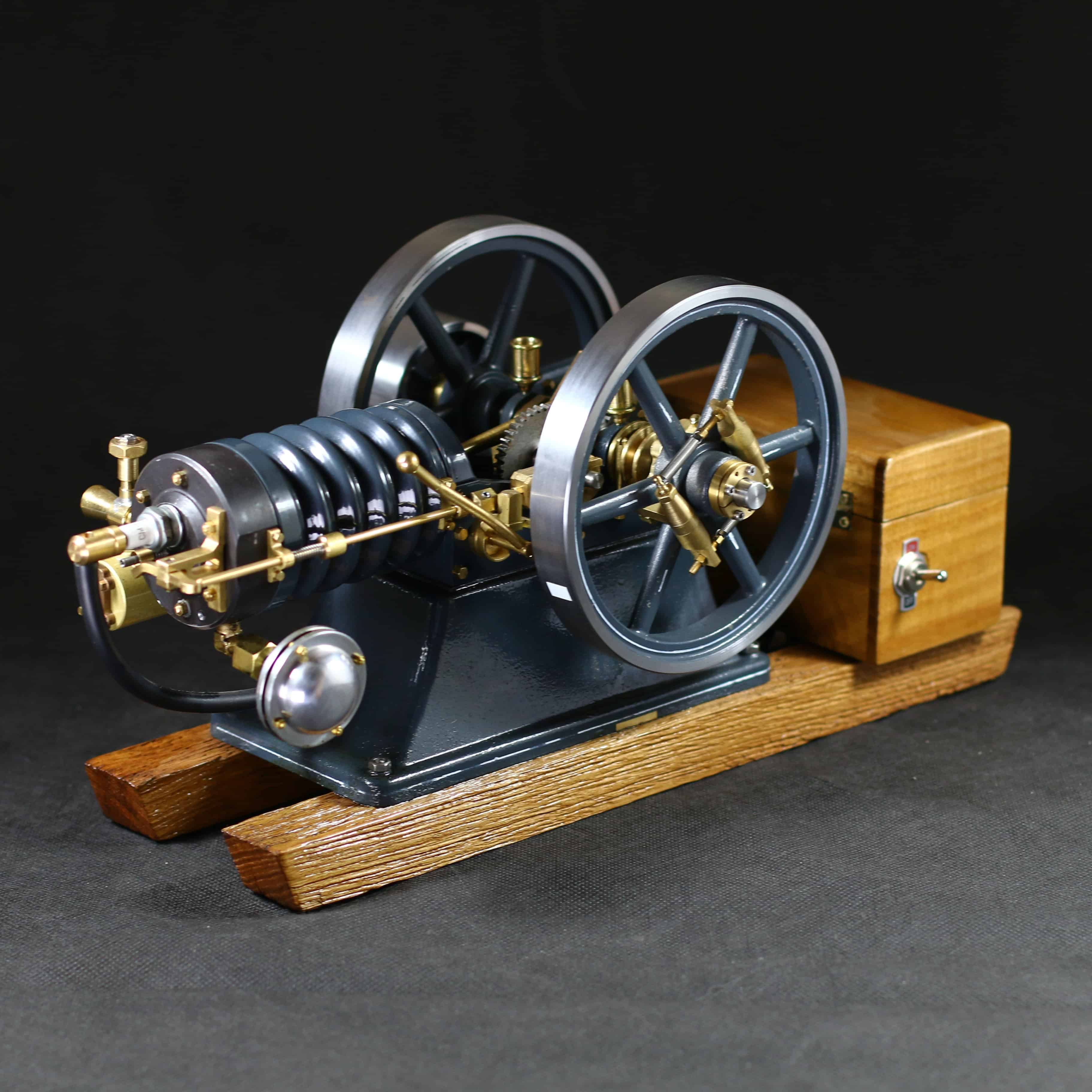
Available again from October 2025 If you're interested, feel free to contact us – we’ll gladly reserve a motor kit for you without obligation. Stationary engine with hit and mismatch were used from 1890 to 1940 for a variety of tasks. The design with lying cylinder, open crankshaft and two flywheels was one of the most popular. These engines have been used in many farms to drive threshing machines, pumps, or grain grinders. But also in many craft and industrial engines, these combustion engines have been used in various sizes. Particularly in the American area, the speed control system has been widespread through a misfire control. The open crankshaft and the open rocker arms allow a very good view of the workings in an internal combustion engine. With the material kit for the internal combustion engine "Karl" you can build a fully functional combustion engine. The material kit contains all required parts including the ignition. The engine has a functioning speed control, which is controlled by a hit and miss misfire control. The ignition is concealed in the base of the machine, as well as in the wooden box behind the machine base. Dimensions of the model internal combustion engine 'Karl': Height with wooden runners: 192mm Overall length: 440mm Width overall: 180mm Length without skids and wooden box: 283mm Dia. Piston: 25mm Flywheel D .: 140mm Speed: 600-1500 rpm The machine foot of the station motor is a heavy gray cast iron base. The piston of the machine is also made of gray cast iron round material. The cylinder is made from a hydraulic cylinder tube which is already finished on the inside and has an excellent surface. The cylinder head and cooling jacket are made of aluminum to guarantee good heat dissipation. The flywheels are made of cast steel in the usual Bengs model construction quality. Most attachments and machine frames are made of brass. All necessary materials for the construction of the internal combustion engine "Karl" Screws, springs and ignition parts are included in the kit. All milling parts are prepared so that they are only deburred and possibly drilled. Construction of the Hit & Miss engine requires a lathe, a drilling machine and a gas burner for soldering. Furthermore, the following hand tools still needed (taps M2, M3, M4, M8x0,75, M10x1 Dies M2, M3, M4, M8x0,75, M10x1 Reamer 3H7, 4H7 6H7, 10H7) files and a set of drill bits needed. Only one side cutter requires a stripping plier and a soldering iron for wiring the ignition. If you want to find out in advance what steps need to be performed in the production of this engine that you see in our Bengs model magazine the building report from the 4-stroke stationary engine "Karl" on. On this page you can see the illustrated report how the station motor is edited.Included in the delivery are: Finished CNC milled milling parts Raw material for the turned parts Raw casting for the flywheels Raw casting for the belt pulley Two wooden runners All required screws, nuts, sprockets and ball bearings Drawings Internal combustion engine "Karl" (24 sheets) and english construction manual (11 sheets) Wooden box for ignition Ignition coil, condenser, spark plug and breakers All required cables for the ignition Power supply for the ignition Hit & Miss regulation The Hit & Miss regulation can limit the engine's maximum speed. When the engine has reached an excessive speed, a slider prevents the exhaust valve from closing. Thus the motor runs freely. No compression in the cylinder chamber can occur and the engine does not suck up any fresh gasoline or ignite the air fuel mixture. The Hit & Miss regulationt is mentioned in the German suspension rules. The intermittent control system was used from 1890 to 1940 mainly in the USA by different companies with internal combustion engines.